Precision is a very critical aspect of engineering and manufacturing. The slightest deviation from the specified measurement may affect functionality and the performance of a component. This is where mechanical engineering tolerances become very important. Engineering tolerances define the acceptable limits of variation of physical dimensions, shapes, or properties of a component. These tolerances ensure that parts fit and function properly in an assembly and that the final product meets the specified requirements. Tolerances are necessary to ensure interoperability between parts, especially in industries such as automotive, aerospace, and the manufacturing of machinery.
This paper discusses the different types of tolerances with a focus on classification and specific uses in engineering.
What is Tolerance in Engineering?
Tolerance is the allowed deviation of the actual size, shape, or position of a part from its ideal size, shape, or position. In the process of manufacture, because of such factors as machine accuracy and operation procedure, the actual size of the part cannot completely meet the design requirement. In that case, A range of deviation is allowed to ensure good functionality and interchangeability of parts. The tolerance value is equal to the difference between the upper and lower allowable values.
Let’s take an example to illustrate what tolerance is. Suppose you are processing a metal round bar with a length of 100mm. Even if you intend to process all of them into the same shape, it is impossible to process all of the metal bars into exactly 100mm because of deviations in size and shape. Although designers and manufacturers have been working to reduce such deviations, they still cannot reduce the deviations to zero.
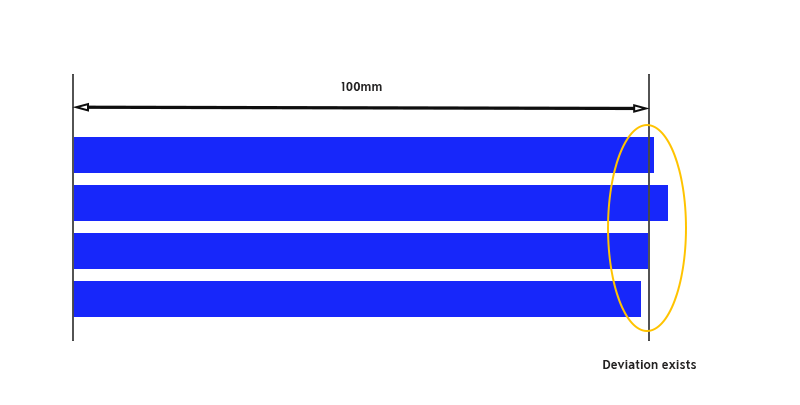
Such deviations in size and shape basically fluctuate up and down around the target value. Therefore, depending on the use of the metal bar, the upper limit allowable value (+1mm) and the lower limit allowable value (-1mm) allowed relative to the target size are determined. The difference between these two values (2mm) is called tolerance.
Types of Tolerance
There are 4 types of tolerances: Dimensional tolerance, geometric tolerance, and fit tolerance. Each type of tolerance focuses on different aspects of a part to ensure that the part has the appropriate functionality in different working environments.
Dimensional Tolerance
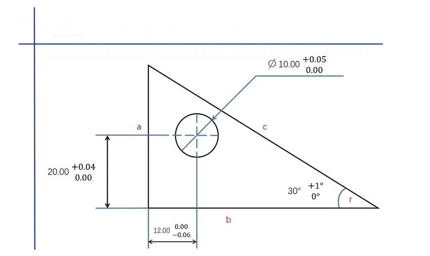
Dimensional tolerance refers to the tolerance applied to the dimensions marked in the drawing, dimensional objects such as length, distance, position, angle, size, aperture, fillet and chamfer, etc. It is used to indicate tolerances different from general tolerances. Unlike general tolerances, dimensional tolerances have no clear standards and can be arbitrarily specified according to the designer’s intention, but the range of achievable tolerances is limited depending on the processing method, etc. Dimensional tolerances include 2 types, bilateral tolerances and unilateral tolerances.
Bilateral tolerance
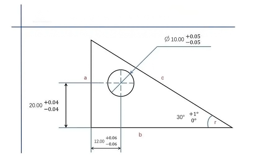
Bilateral tolerance refers to the allowable variation of a dimension that exists within a specified range on either side of the reference dimension. In other words, the dimension may vary in both the upper and lower directions relative to the reference dimension.
Example of bilateral tolerance: If the basic size of a hole is 10mm and the bilateral tolerance is ±0.05mm, then the actual dimension range of the shaft is 9.95mm to 10.05mm.
Unilateral tolerance
Unilateral tolerance, however, refers to the allowed variation of a dimension to be on only one side of the basic dimension; that is, the acceptable tolerance range is limited to one direction.
Example of unilateral tolerance: If the basic size of a hole is 10 mm and the unilateral tolerance is +0.05mm, then the actual size range of the hole is from 10.00 mm to 10.05mm.
Geometric Tolerance
Geometric tolerance not only addresses the dimensions of the component but also delineates the precision concerning the shape, position, and orientation of the part. It guarantees the fidelity of the geometric configuration stipulated in the design of the component and is typically implemented with attributes such as straightness, flatness, roundness, and positional accuracy. The primary purpose of geometric tolerance is to maintain the precision of both the shape and position, thereby preventing issues related to improper fitting of the components.
Geometric tolerances can be divided into four categories: form tolerance, orientation tolerance, location tolerance, and runout tolerance, which in total consists of 13 types.
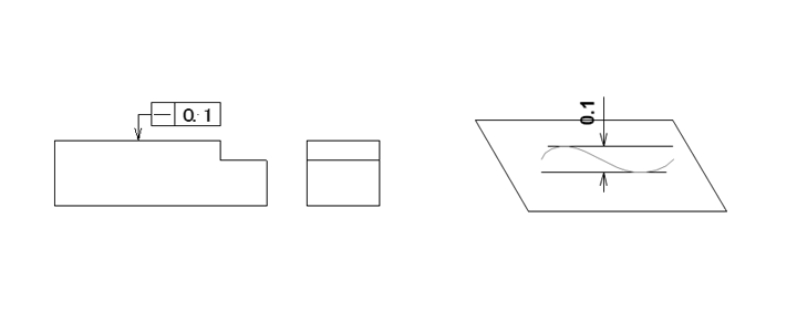
Linearity
Linearity is the allowable deviation from a straight line over a specified length or surface. It is used to define how much a feature of a part can vary from being perfectly linear.
Example of linearity: In a given plane, the line segments to be inspected shall lie between two parallel lines at a distance of 0.1mm.
Flatness
Flatness is a geometrical condition that defines the deviation of a surface from an ideal plane. It provides a metric of how much the surface deviates from ideal flatness, and thus it represents the homogeneity of a surface over its whole area.
Example of flatness: This surface shall be between two parallel planes separated by only 0.3 mm.

Roundness
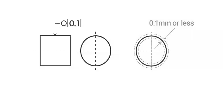
Roundness, also commonly called circularity, is the geometric condition that defines the extent to which the form of a feature, such as a cylinder, hole, or sphere, departs from a perfect circle in any given cross-section.
Example of roundness: The outer circumference of any cross-section of a shaft cut perpendicularly shall fall between two concentric circles just 0.1mm apart on the same plane.
Cylindricity
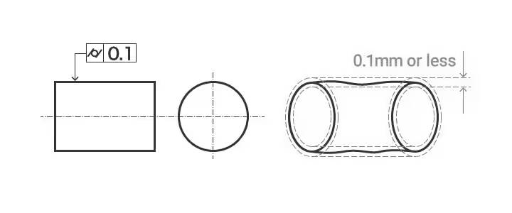
Cylindricity is a geometrical condition that measures the extent to which the form of a cylindrical feature conforms to that of an ideal cylinder. It measures the uniformity of the surface both along the length and around the circumference of the cylinder.
Example of cylindricity: The target plane has to be in between two coaxial cylinders only 0.1 mm apart.
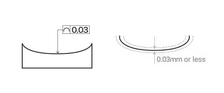
Profile of line
The profile of a line is the condition required to retain the perfect form of a curve of any shape on a prescribed plane of a part. Profile tolerance of a line The allowable deviation of the actual contour line of a non-circular curve.
Example of profile tolerance of a line: The projected profile on any cross-section parallel to the projection plane shall lie between the two envelopes created by a circle of diameter 0.03 mm, centered on the line that has a theoretically exact profile.
Profile of plane
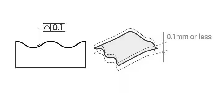
Profile of a plane is the condition of maintaining the ideal shape of any curved surface on a particular part. The profile tolerance of a plane is the permissible variation of the actual contour line of a non-circular curved surface from the ideal contour surface.
Example of profile tolerance of a plane: The destination plane should lie between two envelope planes created by a sphere with a diameter of 0.1 mm, whose center is on the plane having a theoretically perfect profile.
Parallelism
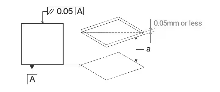
Parallelism is the acceptable variation (deviation) of a feature (e.g., surface, axis or line) with regards to being parallel from a designated reference (e.g. a datum plane, axis, or line). Whilst, it looks like flatness has been discussed again, parallelism involves datum(reference plane or line).
Example of parallelism: The plane identified by the indication arrow must be parallel to datum plane A and lie between two planes that are only 0.05 mm apart in the direction of the indication arrows.
Perpendicularity
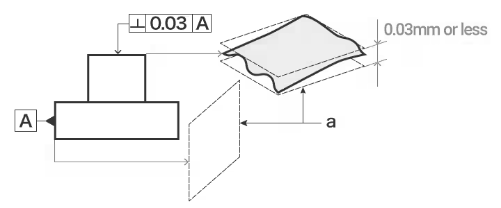
Perpendicularity is a geometric condition that assesses the degree to which a feature, such as a surface, axis, or line, aligns at a right angle (90°) to a reference feature, which may include a plane or axis.
Example of perpendicularity: The plane represented by the indicating arrow shall be located between two parallel planes that are perpendicular to datum plane A, with a diameter of 0.03 mm.
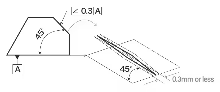
Angularity
Angularity is a geometric condition that measures the amount that a feature, such as a surface, line, or axis, is oriented at an assigned angle, other than 90° (perpendicularity) or 0° (parallelism), with respect to a reference datum.
Example of angularity: The plane indicated by the indication arrow shall be theoretically exactly angled by 45 degrees to the datum plane A and between two parallel planes only 0.3 mm apart in the direction of the indication arrows.
Position
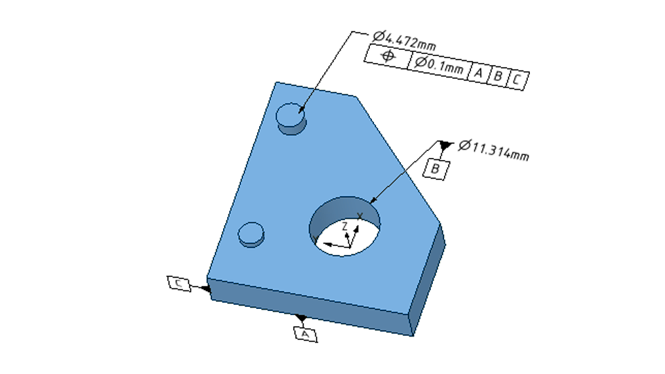
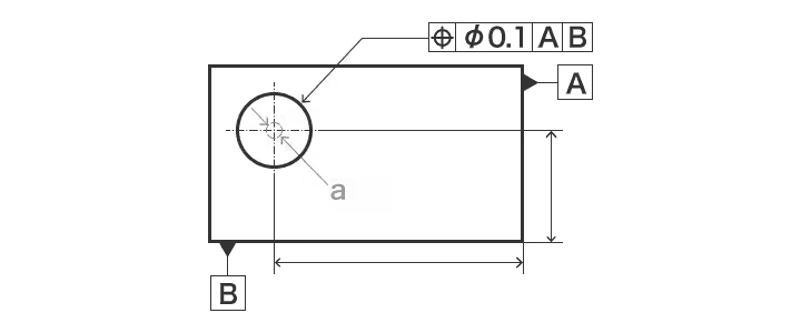
Position is used to find the exact location of a component’s point, line, and surface relative to a reference.
Example of position: The center of the circle shown by the indication arrow shall be within a circle having a diameter of 0.1 mm.
Coaxiality
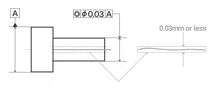
Coaxiality ensures that the axis of a cylindrical feature, such as a shaft, hole, or tube, coincides exactly with the axis of a reference datum.
Example of coaxiality: The axis of the given cylinder shall lie within a cylinder that uses datum axis line A as its axis and has a diameter of 0.03 mm.
Symmetry
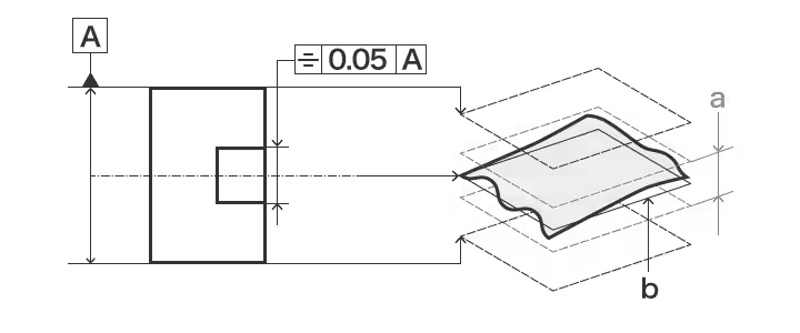
Symmetry measures the evenness with which a feature, or set of features, is distributed about a central reference axis, plane, or point.
Example of symmetry: The center plane marked shall be between two parallel planes symmetric to datum center plane A and separated from each other by 0.05 mm.
Runout
Runout measures the total deviation of a feature’s surface when it rotates about a reference axis. There are two kinds of runout: circular runout and total runout.
Put Your Custom Parts into Production Today!
Circular runout: This is a measurement of how much the surface of a rotating part varies at a given cross-section or plane perpendicular to the axis of rotation.
Total runout: This is the measurement of the variation existing on the whole surface of a rotating component down its longitudinal axis. It combines the effects of circular runout with those caused by straightness or taper irregularities.
Fit Tolerance
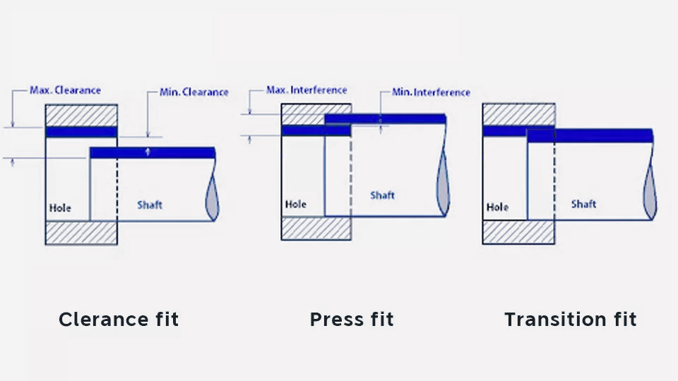
Fits are the relationships between the tolerance zone of pairing holes and shafts at the same basic size. Or we can say that fits are the clearance between the hole and shaft pairing. The clearance can be both positive and negative. The size of the clearance determines whether the two paired parts can move or rotate independently of each other or, are temporarily or permanently connected.
There are three types of fits: clearance fit, transition fit, and press fit(interference fit).
Clearance fit: The tolerance zone of the hole is above that of the shaft, in other words, the hole is larger than the shaft.
Press fit: The tolerance zone of the hole is below that of the shaft, in other words, the shaft is larger than the hole.
Transition fit: The tolerance zones of the hole and shaft overlap. Any pair of holes and shafts may achieve a clearance or a press fit.
For PDF of types of tolerance, Click Here to Download >>
Conclusion
Engineering tolerances have a fundamental place in design and manufacturing, as only high-quality parts are supposed to be produced. Parts that can be assembled at the right precision and function properly, even after certain variations inherent in any manufacturing, must be achieved. Tolerances contribute to product consistency and reliability by defining the allowable variations in size and form. Understanding the different types of tolerances—dimensional, geometric, and fit—is very important for an engineer or manufacturer to be able to set proper tolerance levels for the various components, given the functional requirements of the final product. Be it the precision of aerospace components or the fitment of automotive parts, mastering the application of tolerances forms an integral part of proficient engineering and superior manufacturing.
