Surface roughness (Ra) is the measure in micrometers of the microscopic peaks and valleys in the surfaces of materials, it describes microscopic irregularities on material surfaces. Surface roughness plays a vital role in functional performance, for example, improper surface roughness will cause early failures and diminished load-bearing capacity of the grooves on bearing rings. This article discusses the basics of surface roughness, measurement techniques and how to make a choice.
What is Surface Finish?
Surface finish is composed of three distinct elements – roughness, lay, and waviness However, it is not uncommon in machine shops for the term surface finish to be used to describe only surface roughness. Roughness is the most commonly specified aspect of surface finish.
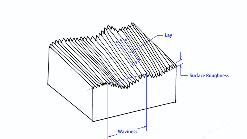
Lay
Lay is the term used to describe the dominant pattern on a surface and the orientation of that pattern. Lay is generally produced by the manufacturing process and can be parallel, perpendicular, circular, crosshatched, radial, multi-directional, or isotropic (non-directional).
Lay refers to the primary pattern on a surface and the orientation of this pattern. It is usually a by-product of the manufacturing process. The different types of lay can be parallel, perpendicular, circular, crosshatched, radial, multi-directional, or isotropic (without any preference direction).
Waviness
Waviness refers to those surface finish variations that are most broad in spacing. In most generalizing ways, periodic irregularities on the surface are larger than the sampling length used for the measurement of roughness. Still, they are less small, shorter and more regulated than to not be flatness flaws. It is common for surface waviness to occur due to warping in the heating and cooling, or due to machining errors said errors being a consequence of chatter or deflection.
Evaluation length is used to measure waviness and a waviness profile is generated in this length. The waviness profile does not include any irregularities in the surface due to roughness, flatness, or form variations. The distance between the peaks of the waves is called waviness spacing (Wsm), while the wave height is established by parameters like average waviness (Wa) or total waviness (Wt). Waviness specifications are less common than roughness specifications, but for bearing races or sealing surfaces they are very important.
Surface Roughness
Surface roughness can be seen as the closely spaced peaks and valleys on a surface, and it is the result of the material condition and production process used.
Criteria for Evaluating Surface Roughness
Sampling Length
The sampling length is a specified reference length used to evaluate surface roughness. It should be chosen based on the actual formation and texture characteristics of the surface. The selected length must accurately represent the roughness features of the surface. When measuring, the sampling length should follow the overall contour direction of the surface. The purpose of defining and selecting a sampling length is to minimize the influence of waviness and form errors on roughness measurement results.
Evaluation Length
The evaluation length is the total length used for assessing surface roughness. It consists of one or more sampling lengths. Since surface roughness can vary across different areas of a part, a single sampling length may not fully represent its roughness characteristics. Several sampling lengths are taken to obtain a more accurate assessment, Typically, the evaluation length includes 5 sampling lengths.
Reference Line
The reference line is the baseline used to determine surface roughness parameters. There are two types:
- Least-Squares Mean Line: Geometric contour line that minimizes the sum of squared deviations of all points within the sampling length. It provides an ideal mathematical representation of the surface profile.
- Arithmetic Mean Line: This line ensures that the areas of the profile above and below it are equal within the sampling length.
The least-squares mean line is the ideal reference line, but it is difficult to apply in practice. Therefore, the arithmetic mean line is commonly used instead. A straight line with a similar position is often used as an approximation during measurement.
Surface Roughness Terminology
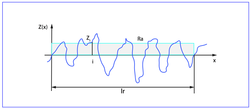
Ra – The numerical average of all the peaks and valleys across the evaluation length. It’s also called the Center Line Average (CLA).
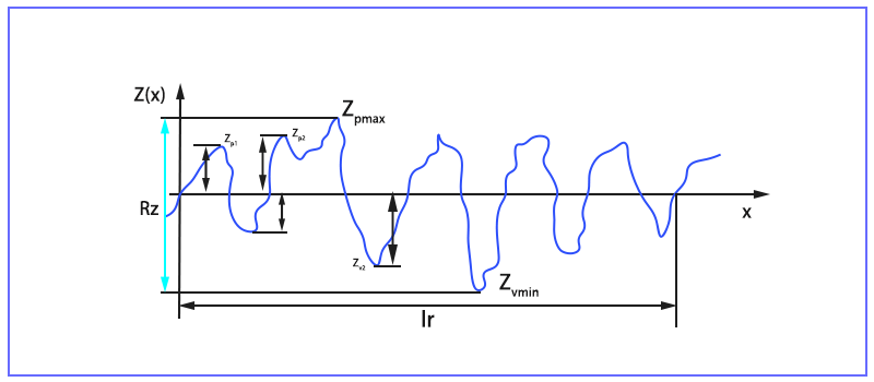
Rz – The average of consecutive highest peaks and lowest valleys. The vertical distance between the highest peak and lowest valley, the distance between the second-highest peak and the second-lowest valley, etc. This is usually done for the five biggest deviations, and then an average is calculated. It helps eliminate errors since Ra is relatively insensitive to some extremes.
Rmax – The vertical distance between the highest peak and the lowest valley, calculated within the sampling length.
Rp – The calculated distance between the profile’s tallest peak and the mean line within the evaluation length.
Rv – The calculated distance between the profile’s lowest valley and the mean line within the evaluation length.
Surface Roughness Conversion Table
The table below represents the conversion between industry-standard units for surface roughness measuring purposes. Awareness about the conversion of one alternative industry-standard unit—for example, surface roughness Ra in metric and imperial—to ISO might well be helpful on how you want your surface finish to be.
| Ra(um) | Ra(μin) | RMS(μin) | Rz(μm) | N scale(ISO 1302) |
| 0.025 | 1 | 1.1 | 0.3 | N1 |
| 0.05 | 2 | 2.2 | 0.5 | N2 |
| 0.1 | 4 | 4.4 | 0.4 | N3 |
| 0.2 | 8 | 8.8 | 0.8 | N4 |
| 0.4 | 16 | 17.6 | 1.6 | N5 |
| 0.8 | 32 | 32.5 | 3.2 | N6 |
| 1.6 | 63 | 64.3 | 6.3 | N7 |
| 3.2 | 125 | 137.5 | 12.5 | N8 |
| 6.3 | 250 | 275 | 5 | N9 |
| 12.5 | 500 | 550 | 50 | N10 |
| 25 | 1000 | 1100 | 100 | N11 |
| 50 | 2000 | 2200 | 200 | N12 |
How to Measure Surface Roughness
There are several methods to measure surface roughness, generally, it can be divided into 4 types: contact measurement, non-contact measurement, comparison with known samples, and in-process methods.
Contact Stylus Profilometer
Contact measurement is the most commonly used method. This diamond stylus moves up and down as it encounters peaks and valleys, the displacement is converted into digital values and displayed on the profilometer screen. This method often measures up to 20mm. Profilometers should not applied for soft or easily deformable surfaces, as the contact may alter the surface texture.
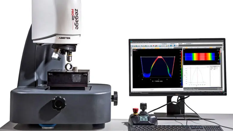
Non-contact methods
The non-contact measurement uses optical or light to measure the surface roughness with direct contact, such as laser scanning confocal microscopy and laser triangulation. A beam is projected on the surface to measure diffraction and reflected signals. these methods are ideal for soft material, and complex geometries for their non-contact to the surface. However, the accuracy is easily affected by the reflectivity and color of the surface.
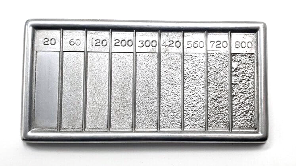
Comparison methods
Comparison methods use surface roughness samples generated by specific processes or equipment. manufacturers can evaluate roughness parameters by comparing the surface against the sample with tactile and visual senses.
In-process methods
in-process methods such as inductance, which measures surface roughness using magnetic materials and electromagnetic energy. Then, the parametric value measured can help find out comparative roughness parameters.
How to Choose the Suitable Surface Roughness?
In some applications, surface roughness may not matter much. However, it holds significant importance in several other scenarios. In critical uses, surface roughness can have an impact on the functionality, performance, durability, and appearance of parts. It also affects the machining time and cost.
The requirements for the surface roughness level in CNC machining vary depending on different applications. There is no such thing as an inherently good or bad surface roughness level; instead, it all boils down to whether it meets the specific requirements. Thus, determining the appropriate CNC machining surface roughness for your part is of great significance. The following factors should be taken into account during the selection process.
Functionality and Purpose
When choosing the right CNC machining surface roughness, the intended use of your part is the most important consideration. Surface roughness can affect the characteristics of your part and how it interacts with other parts and the working environment. It can influence the friction coefficient, noise levels, wear – resistance, absorption capacity, optical properties, load-bearing capacity, durability, electrical conductivity, lubrication, and many other functions and properties. The table below details the various functions of CNC machined parts, how surface roughness impacts these functions, and the corresponding recommended surface roughness levels.
The table below shows the common roughness for different manufacturing processes.
| Process | Common Ra(um) |
| Grinding | 0.2 – 1.6 |
| Honing | 0.1-0.8 |
| Electropolishing | 0.1-0.8 |
| Polishing | 0.1-0.4 |
| Lapping | 0.05-0.4 |
| Superfinishing | 0.025-0.2 |
| Milling | 0.8-6.3 |
| Turning | 0.4-6.3 |
| Drilling | 1.6-6.3 |
| EDM | 1.6-3.2 |
| Forging | 3.2-12.5 |
| Laser cutting | 0.8-6.3 |
| Extruding | 0.8-3.2 |
Cost and Production Time
Achieving a smoother surface roughness in CNC machining demands more machining work. To obtain low roughness values, slower machine speeds, finer feeds, and shallower cuts are necessary. For Ra levels of 0.4 and below, additional polishing might be required. The precise manufacturing process and these extra steps take more time and effort, which in turn drives up the production cost.