Ever wondered how CNC machines bring your designs to life? Enter G-code, the language that serves as the conductor for these manufacturing processes. While digging into the details of G-code commands might not be the priority task on your agenda, having a solid understanding of the basics can help a lot to learn what your machine is doing.
What is G-code?
G-code, an abbreviation for “Geometric Code” or “Gestalt Code,” is a fundamental programming language pivotal in Precision CNC machining. This alphanumeric code serves as the critical link between digital design and the physical creation of objects, providing precise instructions to CNC machines.
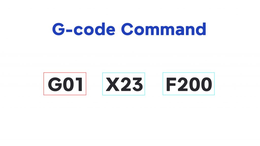
Generated by computer-aided design (CAD) or computer-aided manufacturing (CAM) software, G-code guides CNC machines through the nuanced process of shaping raw materials into finely detailed, high-precision products. Each G-code command signifies a specific action or function, contributing to the overall precision of the manufacturing process. For instance, the G00 command directs the machine to achieve rapid positioning with utmost accuracy, while G01 facilitates linear interpolation, guiding tools along meticulous paths. G-code extends beyond mere movement commands. It also encompasses instructions for spindle speed control, tool changes, coolant flow management, and other critical aspects. This versatility allows manufacturers to program intricate geometries and complex sequences, ensuring the precision demanded by modern manufacturing standards.

Common G-codes in CNC Machines
The following list covers a wide range of G-code commands used in CNC programming. Keep in mind that the availability and behavior of commands can vary between different CNC machines and controllers. Always refer to the machine’s documentation for precise details and compatibility.
Motion Commands
G00: Rapid Positioning
G01: Linear Interpolation
G02: Circular Interpolation (Clockwise)
G03: Circular Interpolation (Counterclockwise)
G04: Dwell
G10: Coordinate System Data Input
G17: Select XY Plane
G18: Select XZ Plane
G19: Select YZ Plane
G20: Inch Units
G21: Metric Units
G28: Return to Home
G30: Return to Secondary Home
G53: Move in Machine Coordinates
G54-G59: Work Offsets
Control Commands
M00: Program Stop
M01: Optional Stop
M02: Program End
M03: Spindle On (Clockwise)
M04: Spindle On (Counterclockwise)
M05: Spindle Stop
M06: Tool Change
M08: Coolant On
M09: Coolant Off
M30: Program End and Rewind
Unit and Measurement Commands
G90: Absolute Programming
G91: Incremental Programming
G92: Set Position
G92.1: Cancel G92 Offset
G92.2: Cancel G92 Offset and Set Current Position
Speed and Feed Commands
G93: Inverse Time Feed Mode
G94: Feed per Minute Mode
G95: Feed per Revolution Mode
S: Spindle Speed
F: Feed Rate
Cutter Compensation and Offsets
G40: Cutter Compensation Cancel
G41: Cutter Compensation Left
G42: Cutter Compensation Right
G43: Tool Length Compensation Positive
G44: Tool Length Compensation Negative
G49: Tool Length Compensation Cancel
Advanced Motion Control
G05: High-Speed Machining
G61: Exact Stop Mode
G64: Continuous Path Mode
G68: Coordinate System Rotation
G69: Coordinate System Rotation Cancel
G73-G89: Peck Drilling Cycles
Customization and Flexibility
G96: Constant Surface Speed
G97: Spindle Speed in RPM
G98: Return to Initial Z Level in Rigid Tapping
G99: Return to R Plane in Rigid Tapping
G10 L2: Coordinate System Offset Setting
G53: Move in Machine Coordinates
Common CNC G-code Errors and how to eliminate it
CNC G-code programming, while powerful and versatile, can sometimes lead to errors that affect the machining process. Understanding common G-code errors and their solutions is crucial for efficient CNC machining. Here are some typical errors.
Syntax Errors
Syntax errors in G-code, such as missing spaces or incorrect command structures, have the potential to create interpretation issues for the CNC machine. To address this, a meticulous review of the G-code, checking for typographical errors and ensuring precise spacing between commands and values, is crucial. Additionally, leveraging debugging tools and simulation software aids in identifying and rectifying syntax errors proactively, minimizing the risk during the actual machining process.
Unsupported G-code Commands
Using G-code commands not supported by the CNC machine can lead to unexpected behavior; therefore, it’s crucial to consult the machine’s documentation diligently, identifying supported commands and replacing any incompatible ones with alternatives to ensure a smooth and error-free integration with the CNC machine.
Toolpath Overlaps
The challenge of overlapping toolpaths, with the potential for collisions and unintended cuts, poses a risk to the machining process. To mitigate this risk, it’s essential to leverage CAM software, enabling visualization and optimization of toolpaths to eradicate overlaps. Additionally, careful adjustment of tool clearances and verification of toolpath strategies are imperative steps to prevent tool collisions and ensure the production of a smooth and accurate finish.
Incorrect Work Offsets
Incorrectly set work offsets pose a risk of tool misalignment, leading to inaccuracies in cuts and dimensions. To address this, a comprehensive approach involves thorough inspection and adjustment of work offsets (G54-G59) to align precisely with the desired zero points, emphasizing the critical importance of selecting the correct work offset before initiating the program for precision in machining.


